Features
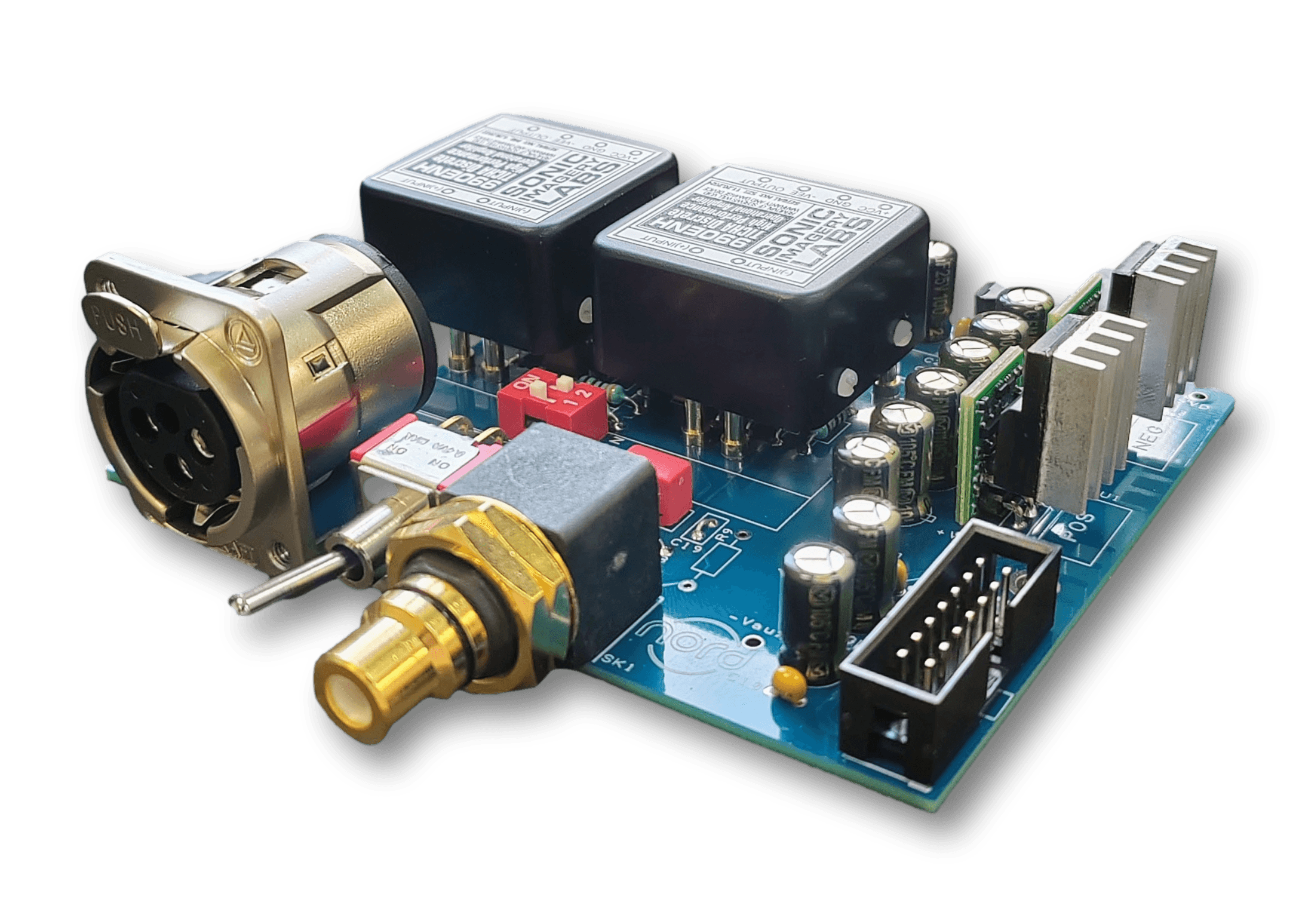
Onboard input sockets (short signal path)
4 level two way dip switch buffer gain selection – high, normal, low and unity (which equates to 32.2dB 29.0dB 23.8dB and 14.4dB total amplifier module plus buffer gain)
Wima metallised film polyprop feedback capacitors
Panasonic FM low ESR bulk supply capacitors with 0.1uf ceramic bypass capacitors
Hand matched gain/feedback resistors (<0.1%)
8 pin DIL and 990 type op amp sockets (Weiss OP-2 compatible)
Sparkos SS7815/SS7915 Discrete Voltage Regulators for +/-15V op amp supply rails
Separated and pi filter isolated pre-regulated 5V analogue and 5V digital supply
Input Options
XLR only (standard)
XLR and RCA switchable (optional)
Choice of Op Amps
Texas Instruments SoundPlus OPA1612 (BJT) or OPA1656 (FET) – on SOIC to 8 pin DIL converter x1 per buffer
Sparkos SS2590 (BJT) – Discrete Class A x2 per buffer
Sonic Imagery SI990 (BJT) or SI995 (FET) – ENH TICHA Discrete Class A x2 per buffer
Weiss OP-2 (FET) – Discrete Class A x2 per buffer*
*If Weiss option is chosen the Sparkos regulators will require extra heatsinking, preferably attached to casework base, and therefore will be supplied separately, not fitted.
Other op amps can be used but will need to be assessed for compatibility/performance by the user and at the user’s risk.
There are two main types of op amp input circuit BJT or FET, whilst the choice is left to the user, certain conditions with source input type (op amp input bias current causing small DC offsets) will favour FET.
For best CMRR performance the buffer can be driven from an impedance balanced or a fully active balanced/differential preamplifier output stage with both hot and cold driven equally (the latter being our preference).
The 20 pin IDC connector is positioned so that it lines up with the 1ET9040 buffer input connector meaning the 20 way ribbon cable can be as short as possible.
The 14 pin IDC connector is to accept DC from the power supply and requires an ‘amp enable’ pull low signal which is directly compatible with Hypex SMPS1200A180 (using a 10 way to 14 way IDC ribbon cable).
These cables can be supplied to required length on request.
Dimensions
99mm wide x 80mm deep
PSU Requirements
+/- 17V to 24V 100mA+ unregulated or regulated
Buffer board J1 14 pin IDC header connects to suitable supply
Pin 1 +Vin
Pin 2 -Vin
Pin 3 GND
Pin 6 Amp Enable Input (use a ‘pull low’ signal to enable or connect to GND)
Two buffer boards will be required for stereo